

Raking It In


As the science of off-road racecar building moves ever-further down the road towards smaller, lighter vehicles that look like superminis on steroids, Rakeway Engineering is developing a truck which blends a more old-school approach with the very latest in technology. And the results are already there to be seen…
Over the last few years, there’s been a trend among Britain’s off-race car builders towards designing vehicles that look more and more like everyday superminis. During this time, however, one company based in Stoke-on-Trent has developed a vehicle that bears more of a resemblance to compers that were being built in individuals’ garages and yards not so many years ago.
That’s not to say that the vehicle in question was thrown together from parts that were laying around the yard, or had the side of an old filing cabinet being bent around a telegraph pole to form the transmission tunnel. Instead, it’s a well executed and refreshing change to the ever-present march of UK off-road racing towards the ever-blurring threshold between rallying and our traditionally more arduous terrain-covering sport.
The vehicle I refer to is the Rakeway Ridgeback, this initially being the brainchild of Neale Richardson of Rakeway Engineering. Astonishingly, it has achieved its outward appearance while still challenging, and even beating, the modern Eurobox lookalikes. Beauty is of course in the eye of the beholder, and this is a controversial subject that’s debated over many a pint of bitter, but there’s something about the Ridgeback that caught my eye from across the exhibition hall at the 2008 British Indoor 4x4 Show. There’s something of a return to the style of belt and braces fabrication that I like.
A brief history of Neale would show him with an early interest in all things mechanical, and he served an apprenticeship as a toolmaker with Rolls Royce before moving on to the railway and then the ceramics industry. During this time, he built two rally cars and a few motorbikes before catching the Land Rover bug. This led to his building a trialer in 1992, before then campaigning an early Bowler comp motor from 1993 until Foot and Mouth shut the sport down in 2001. Shortly after competition recommenced, he badly damaged the Bowler, and this started him down the track that led to the birth of the Ridgeback.
Along the way, in 2004, Neale teamed up with two other engineers from a ceramics industry background to form Rakeway. The company operates from a 2000 square foot premises equipped with modern CNC equipment and, believe it or not, a tube bender that they built themselves! Their preferred field of operation is motorsport engineering, but they also take on vehicle restoration or specialist projects.
Neale’s brief to himself while planning the vehicle was that it should be able to stand the rigours of off-road racing while at the same time showcasing some of what Rakeway can do. To do this, he decided to design an independently sprung racer, using suspension geometry software to create a computerised model giving what he felt was a good combination of anti-dive, anti-squat, roll control and traction potential.
Even then, he accepted that the vehicle would inevitably be a process of continuous development and evolution. Three racers have to date been built; reflecting this, the third has a slightly updated layout.
This is where Ian Roberts comes into the story. Neale credits him 50/50 with the design of the frame and further development of the vehicle as a whole. Ian previously had a Mattserati, but wanted something to accommodate a larger powerplant, also deciding it should be longer, wider and lower.
They initially designed the cockpit area around all the required elements such as seats and steering wheel, then laid the mechanical components in place. The frame was formed around these parts, constantly adjusting from CAD drawings to reality. Having got a frame on the floor, they downsized things to where they ended up with their finished frame design.
Two things then happened. First, they got a grant from MAS – the Manufacturing Advisory Service – which paid for Ceram Research in Stoke to do a structural analysis on the frame. This took a 3D CAD model and put it through a series of tests to assess frontal impact at two speeds, side impact and impact along the front hoop top corner to rear hoop top corner line. Information provided to Ceram included tube specifications and educated guesses at mass locations around the vehicle.
On a personal note, I’ve always had a hankering to perform what I’d consider to be the ultimate test of these computer simulations and place the computer operator in the car he’s just said was fine, then push it off a cliff. But maybe that’s just me! Anyway, the end result was basically that after a 60mph impact into an immovable object, the Ridgeback’s occupants would get out of the vehicle.
The second thing that happened was that Bob and Charlie Evans saw the first frame on the floor and said they wanted one. Charlie is the son of the father-and-son team, and said he would style the body; being a designer working for Land Rover did him no harm here!
Between them, the team produced three sets of fibreglass bodies in the garage of their family home. Incidentally, Bob and Charlie had the first frame, Ian Roberts had the second and Neale himself is intending to run the third, which is nearing completion as I write. All cars were developed in spare time, not company time… which is pretty impressive, even given that there were several people involved. This joint development is ongoing as a group, and is most definitely not just the dream of one man.
Having been so comprehensively modelled and tested in virtual form, the frame was finally fabricated from Trumec full-hard CDS tubing with a minimum yield strength 450 N/mm2. Neale decided to use this tube as he felt it was more precise in terms of tolerances than normally used derivatives of CDS. The only areas this material is not used in are the floor tubing and nerf rail.
Tube sizes are decided on depending on the stresses for components, this coming from the combined gut feeling that results from a collective thirty years’ experience before being proven using CAD. The main objective is for the frame to survive several seasons of competitive use without needing attention (not including damage, of course).
Floor tubing is medium Blue Band 1387. This is because the guys feel that the floor makes contact with the ground more than other areas, particularly the side nerf rail, and a thicker, more malleable tubing withstands impacts better without damaging the main frame. The thicker tubing also allows for thinner and therefore lighter floor plates.
The main hoop’s outside edge is at least four inches outside of the seat line, and everything is triangulated as much as possible. Straight tubes are also used to maximum effect, minimising the use of bent members.
The main and front hoops actually come off the same jig, but the front hoop has legs four inches longer as it sits lower at roof height and is laid back at an angle of 30 degrees to the vertical; this is a great way to simplify component manufacturing processes. The front hoop goes all the way to the lower front corner of the cockpit area, where all front chassis tubes converge, this allowing stresses to transmit away from that point.
On car number three, the rear coil-over and shock absorber mountings are slightly differently designed, mainly to give provision for a larger engine opening. Back towards the front end, the footwells are actually steel plates welded in between the tubes; these are much stronger than aluminium plates fitted to lugs.
The wishbones are again made of Trumec CDS at 1.5 inch diameter, with a varying thickness as required. Neale does not believe in making the wishbones too strong; by making them sacrificial, you stand a better chance of preventing damage to the main frame. They are secured at the inner end using Superpro bushes, these being off the shelf in terms of size but with a modified compound.
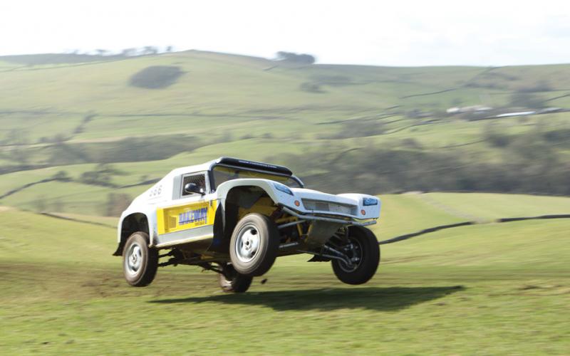
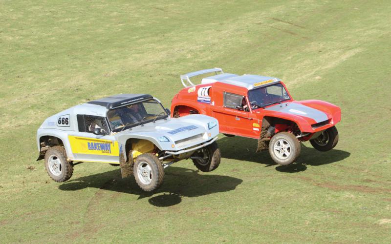
That’s the basic frame of the vehicle (literally), but as is always the case no two examples are exactly the same. Thus we’ll go through the technical make-up of each Ridgeback together, bit by bit. In the pictures, Car 1 is the red vehicle, while Car 2 is silver.
Suspension
- Cars 1 and 2 are on twin dampers all round, each with a two-inch diameter and 12 inches of travel (of which only 10 is actually used at the back). All are coil-overs, but one front shock on each side runs without springs, even though that option is retained.
- Car 1 runs Bilstein shocks, while Car 2 runs Fox.
- Car 3 runs Fox 2.5-inch coil-overs all round, single on the front and twin on the rear (although the latter may be swapped for a bypass shock on each side). There is also a two-inch gas shock here which is being used as a ‘sophisticated’ bump stop, and if this works it may be tried at the front too.
- All these shocks have a 10-inch stroke, so they are now using pretty much full stroke.
- It was found that the front end didn’t need as much springing and damping, even though the rear is only 100kg heavier.
- Each car has 14 inches’ travel at each corner, though it can be maxed out to 17 at the front and 20 at the back if needed. However, Neale doesn’t see any need for this much over the terrain the cars are currently tackling, and there’s no point having it for its own sake as it’s more problematic to control. The cars can be tuned to suit particular events, at any rate, even lowering them and reducing travel if needed.
- Track widths are 72 inches to 74 inches, depending on the rims that are used.
- Wheelbase is 106 inches – a length that will be very familiar to seasoned comp-watchers.
- The billet aluminium suspension uprights are custom made by Rakeway and house Range Rover III wheel bearings because ‘they work well and are easily available.’
- The hubs’ PCD accepts Discovery II pattern wheels, and the front uprights use commercially available king pins, while the rears use the A-frame joints off the rear of a Discovery III. Assisting the geometry design on Cars 1 and 2 are Land Rover anti-roll bars, but Car 3 is being built with an eye to using custom units.
Engine
- Car 1 runs a Chevrolet LS1 5.7-litre aluminium V8 putting out approximately 420bhp, with 347bhp at the wheels. The motor is cooled via a stock TD5 radiator with 12 inch Pacet fans and a Mocal style engine oil cooler.
- Car 2 has a supercharged Jaguar XKR V8 with approximately 400bhp and 330bhp at the wheels. Cooling is via a Citroen van radiator and engine oil is cooled with a fan assisted Radtec oil cooler. Transmission cooling is achieved using a large Jaguar XKR cooler sat in the front end.
- Car 3 has a 6.0-litre Chevrolet LS2 aluminium V8 nestling in its loins, and the power being aimed for is around the 480-500bhp mark. The cooling system components are undecided as yet, but there will most likely be an aluminium radiator involved somewhere.
- All the vehicles run Emerald MD3 engine management systems. These are manufactured in the UK, and Emerald has its own rolling road. All three owners chose this system for several reasons, including keeping the costs down and keeping the learning process simpler, so they all benefit from each other as they progress with tuning and fault finding – not that the systems have thus far given them any faults to find!
Transmission
- Car 1 has a Tremec H-pattern close-ratio TKO 600 manual box with a 7.25-inch triple-plate Super Clutch and a Rakeway custom flywheel. To get things the right way round, the box is controlled by Rakeway’s own modified gearshift. Car 3 has the same set-up, but with a custom bellhousing which is shorter than the original.
- Car 2 runs a ZF 4HP24 auto with an HP24 pump, HP22 main case, Jaguar output case and speed governor. The clutches and internals are HP24, with an HP22 non-electronic valve body, and it’s driven as a manual valve-bodied auto would be. The gate has been altered to lock out of reverse, neutral and park, and engine braking in first gear if available if necessary.
Transfer box
- Cars 1 and 2 have Rakeway’s own remote reverse-rotation transfer boxes, with selectable four-wheel drive. Car 3 has the same, but with permanent four-wheel drive. Output flanges currently accept 1310 propshaft flanges.
- All the transfer boxes have custom-built helical gears. There are versions available with ‘shaven’ gears for higher-performance applications if required, but with these boxes achieving quieter, cooler running through high-accuracy gear cutting and precision thrust control, most needs will be met with the cut gear option. According to Neale, the billet casing is less affected by heat expansion than other variants.
Propshafts
- The props run standard GKN universal joints and run through Rakeway centre bearings. These have high-speed bearings and low-drag seals, minimising the performance potential lost through friction.
Differentials
- Cars 1 and 2 run BTR Automotive limited-slip diffs with 8-inch crownwheels. The output shafts are custom-made by Rakeway to suit the driveshafts; these are stock Range Rover III diesel units, but are modified to achieve higher angles and smoother running – and to be approximately 1.5 kilos lighter.
- Car 3 runs an 8.8-inch Ford Motorsport differential case out of a Racing Cobra Mustang, with an aftermarket limited-slip diff. The input and output flanges are customised, and in time the rear diff cover housing will be replaced with a once-piece billet aluminium unit.
Brakes
- The brakes use Hi Spec Motorsport four-pot calipers; these could go to six-pot if required, but Neale doesn’t feel this is necessary for racing in the UK. Front discs are 305mm Discovery II rears, while at the back there are 285mm units; all have been modified for racing use.
Steering
- All three cars use the same Rakeway steering rack, with a Sweet hydraulic control valve. Cars 1 and 2 have electric hydraulic pumps, though Car 3 may go back to an engine-driven unit to achieve the increased amounts of flow required.
- All cars have 1.8 turns lock to lock, giving quick steering response. Just ahead of the cars’ steering wheels are Rakeway short race steering columns with quick release wheel bosses, and the column shafts accept Land Rover steering joints. Joining all of this to the uprights so the cars can get round the twisty bits are motorsport-spec rod ends (commonly but incorrectly referred to as rose joints), but this area may be subject to change in the future.
Body
- As we mentioned earlier in this article, the bodies are mainly fibreglass. These started life from humble beginnings, as the roof mould plug was originally built up from a modified Range Rover classic roof, and the bonnet mould plug was crafted in a similar method from a Range Rover Sport unit!
- The finished bonnets are constructed from a mixture of random and woven roven matting. The cab sides have a two-inch fire retardant foam filling behind them for impact protection and are covered by an internal aluminium skin. These panels continue ahead of the front hoops, and the resultant voids are filled with expanded foam to give more of a crumple zone ahead of the crews, structures and fuel cells.
- The main hoop firewalls are made from 1.6mm aluminium, as are the rear inner wings, but a combined inner/outer wing made from fibreglass has just been developed.
Fuel Cell
- The cars’ fuel cells are custom built aluminium units. For UK use, a ten-gallon capacity is sufficient, but the potential exists to increase this to nearly twenty if required. The aluminium panels have beads rolled into them for additional stiffness, and the cells have fuel traps in the bottom.
- The two cars currently running have had plenty of fastest times, overall wins and fastest laps in NORC, BCCC and AWDC events to their credit so far, and at the time of writing Ian Roberts had taken four out of four overall wins in the 2009 NORC championship. As time goes on and the third vehicle hits the UK off-road race scene, that’s a trend that looks set to continue.
- In a sport where evolution seems, rightly or wrongly, to be heading away from its roots, it’s heartening to see someone possibly turning the clock back a notch or two to a design overview that somehow seems more attainable by your average off-road racing driver. Like the best vehicles from the early days of comp safari, the Ridgeback combines great strength with great engineering. And, proof of the pudding, it gets results. It’s easy to finish, and it’s easy to go fast; do both, and you’ve got a car that works.
DIY SPACEFRAME, FOX, FOX SUSPENSION, REVERSE-ROTATION TRANSFER BOX, RIDGEBACK


