Suspensions of Disbelief
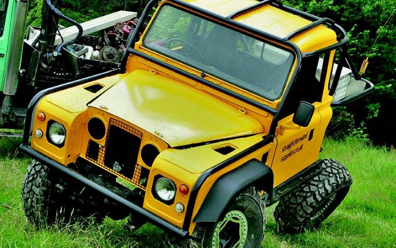
12 set-ups that made 'em sit up: It doesn’t matter what you want your 4x4 to do – its suspension will still be pivotal to how well it does it. But the days when a basic spring and shock lift counted as a ground-breaking set-up are long gone. Here we look at a dozen systems which for one reason or another have been worth a second glance. Pushing the game forward always matters – and so, in this budget-conscious world, does making the most of what you’ve got. Either way, these are the trucks that did it…
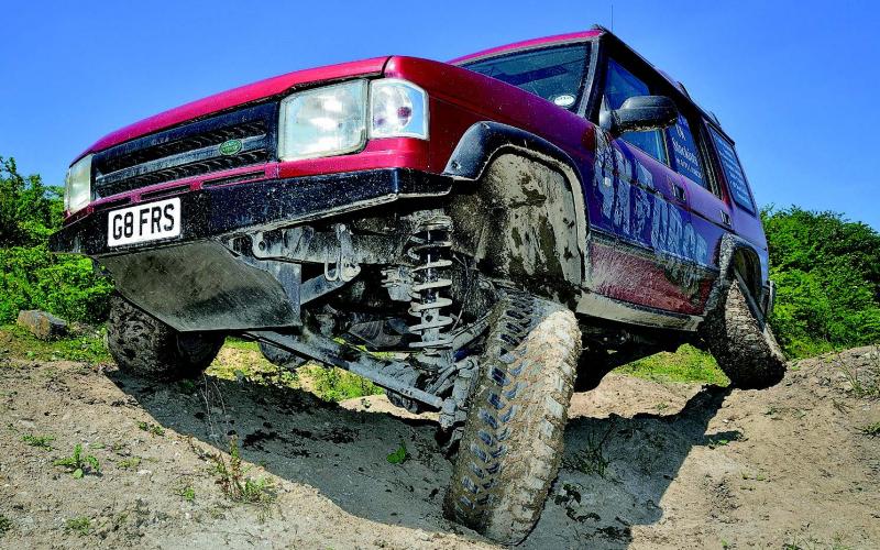
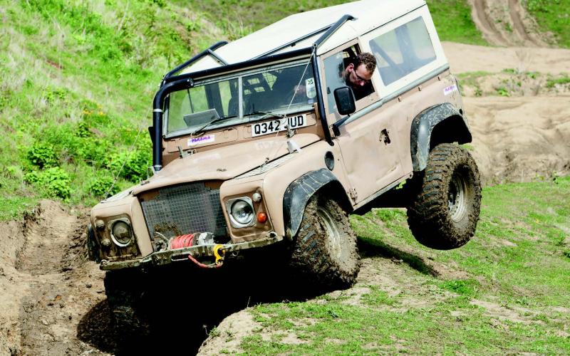
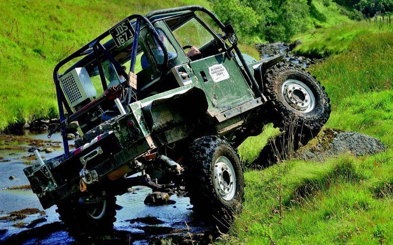
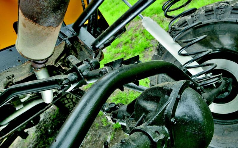
Four-link revolution for Landies
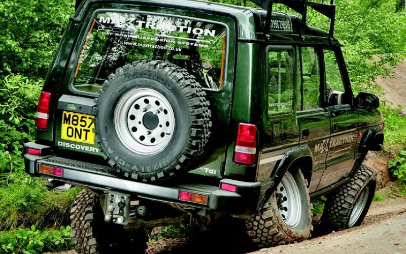
Gordon Jackson is that most promising of things, an engineer who likes off-roading. In fact, he’s an engineer who likes off-roading but stacked his Discovery after one wheel landed in a hole as he crested a hill and the whole thing bounced itself on to its roof.
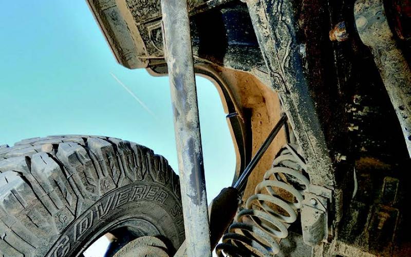
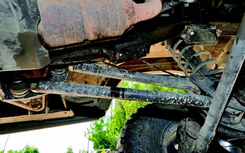
Reflecting on the incident, he saw a problem with the way his truck had responded to the terrain. So he set out to fix it. His first attempt used a 3-link rear with an A-frame, similar to the factory set-up. But he wanted to eliminate axle steer, and he had seen 4-link systems on American rock crawlers.
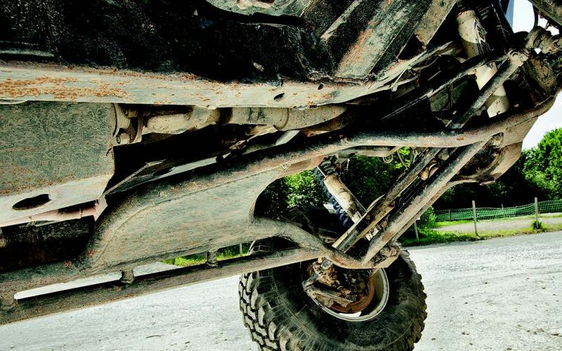
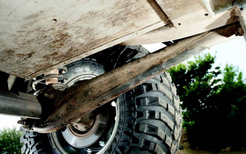
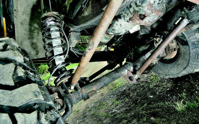
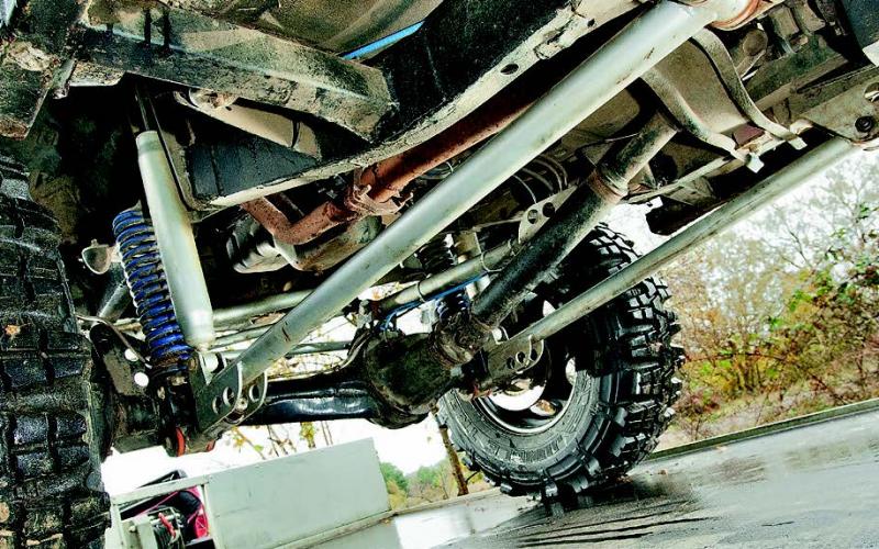
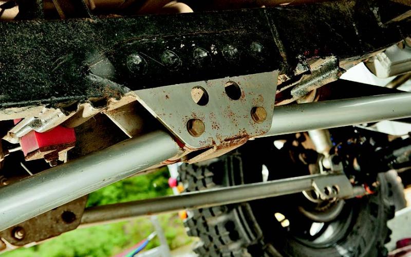
That’s where the idea came from – but the suspension he designed wasn’t a copy of anything. It uses the standard A-frame brackets to mount a pair of clevis joints, which work with a set of fabricated radius arms to control the axle in all three axes of movement.
Naturally, the axle can move up and down as required, whether by the road/ground or the load in the back of the vehicle. That’s the first axis of movement. The second is around a centre point when viewed from either end of the car – what we know as articulation. The third, which is what this system seeks to control properly, is the axle’s movement forward on its radius arms as one side drops out, which gets more pronounced the further it’s capable of drooping.
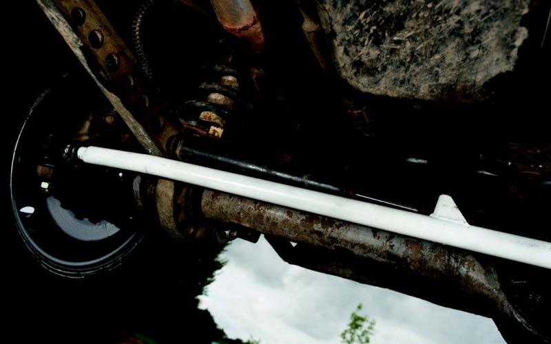
Rather than pivoting around the A-frame joint, the axle moves in an arc controlled by the twin joints that replaced it. Up front, Gordon replaced the traditional radius arms with twin-boom units whose purpose is to maintain the correct castor angle at all times – not just to make up for a suspension lift, but throughout the axle’s arc. Gordon’s argument for this is that the tyre contact patch is never diminished and the steering is never loaded up by the weight of the vehicle shifting around, meaning that however much body roll you might get on the road, its handling will remain vice-free.
The links are all made from CDS, with what Gordon describes as ‘over-specced’ ball joints and standard Land Rover bushes. ‘I prefer metallastic to poly,’ he says. ‘People like poly bushes because they’re soft and look like they’re making up for the tight spots in the suspension. We think that because our suspension is moving without tight spots, we don’t need soft bushes.’
Science 1, axle steer 0
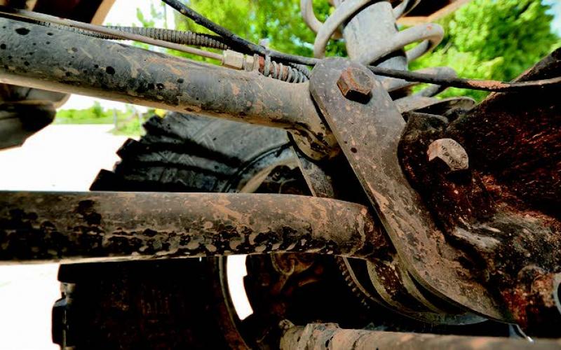
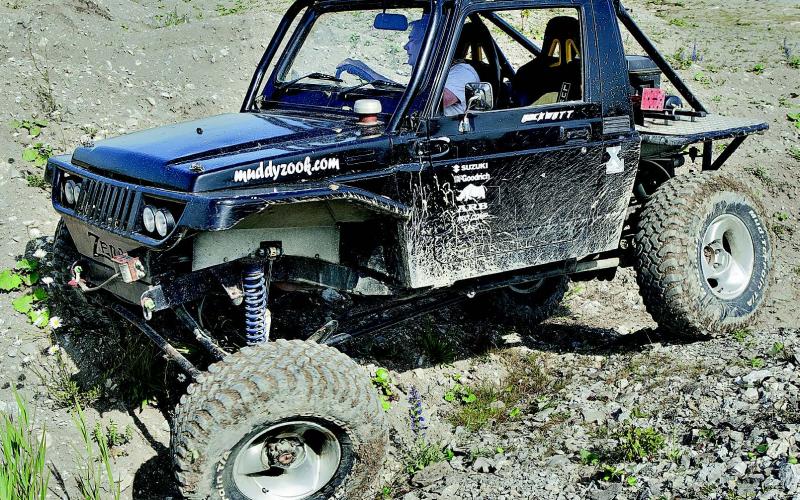
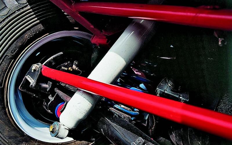
This one’s going to sound like a bit of a science lesson. Or maybe even a history lesson. Either way, it’s going to be worth listening. Back in the days when Richard ‘Rockwatt’ Wattam was just Richard Wattam, he built himself a Suzuki SJ with lots of travel. Alas, as well as lots of travel it had lots of rear-steer. Well, not lots, but some, and as far as an engineer like Richard was concerned that was too much.
‘I put my thinking cap on and designed a completely new suspension set-up from scratch,’ he explained. ‘I didn’t want to just reduce rear steer – I wanted to eradicate it. So for the main rear links I incorporated a cantilever system based on a Scott Russell linkage.’
You know, one of those. And you guessed it, here comes the history. John Scott Russell invented a linkage which converts linear motion to linear motion – in a line which is roughly perpendicular to the input.
While that all sounds reasonably modern, Mr Russell was actually an engineer who worked alongside Isambard Kingdom Brunel on The Great Eastern, the biggest ship in the world at the time, and he also used this linkage on early steam trains like the Puffing Billy of 1813.
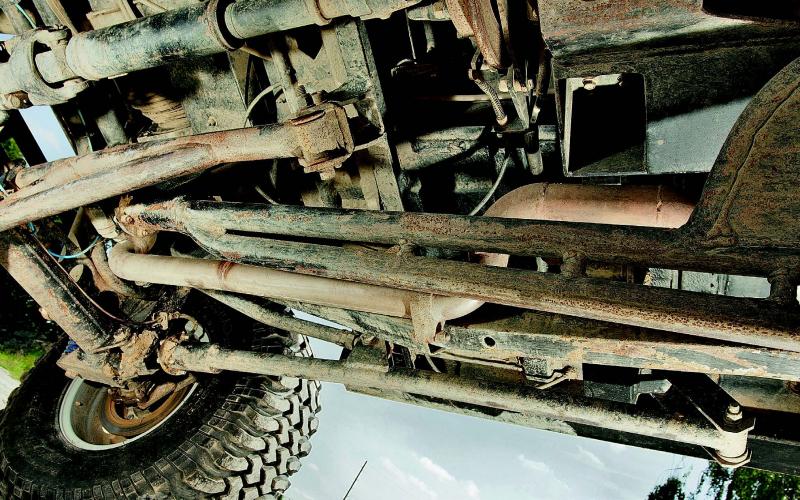
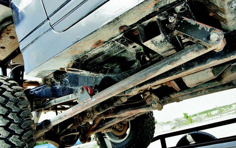
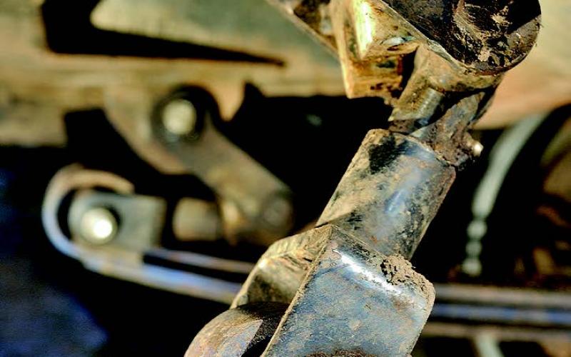
Extraordinary, to think this trick modern 4x4 uses the ideas of a man who was using them before the Battle of Waterloo. Richard takes up the story: ‘This allowed the vertical travel of the axle to be perfectly linear. It did take quite a lot of length calculations to get the required travel, but I got there in the end. ‘At the axle end of these links, I needed some form of joint that would allow movement in all planes with no interference. There is nothing on the market that would do the job, as I needed 42 degrees of rotation in a single joint. So I made a bushed UJ-style joint to take care of the up-and-down and side-to-side movement and a taper bearing swivel assembly, kind of like a wheel hub, that gives a full 360-degree rotation.
‘With the fore and aft location taken care of, next it was the turn of the axle’s rotational location. The central traction bar I used for his needed to extend and swing from side to side with the axle articulation, so I employed a shackle with three bushed pivots to move in all the required directions, again with no interference.’
The final element was a panhard rod with symmetrical pivot points, which Richard mounted high for stability and protection. So that’s the rear-steer taken care of. Up at the front end of the vehicle, Richard used a one-link system similar to that found on Unimogs. But once again, he did it with a nod to the past.
Meet Rudolph Ackerman. He patented a steering arrangement which focused on the front wheels having to turn in circles of differing radii. Today, we talk about Ackerman geometry (the crucial angle is the one between straight-ahead and an imaginary line drawn through the steering hub and the centre of the rear axle), but he was just the inventor’s agent – actually it was invented by Georg Lankensperger. Bit of a close call there, really.
Anyway, Richard needed to get the best possible Ackerman angle so that the car would steer as naturally as possible. He did this by mounting the track rod behind the front axle and placing the main front suspension pivot a mere six inches ahead of the rear axle. After that, it sounds a bit mundane to mention that as at the back, Richard used a panhard rod to control the front axle in the lateral plane. He did, though.
The suspension’s movement was handled by a set of Pro-Comp shocks with 12” of travel at the front and a whopping 14” at the rear. At the top of these rear units, Richard installed a pair of pneumatic cylinders for controlled dislocation – these were rigged up so they could be shut off to lock them in position or, in the frankly rather unlikely event of the Suzuki getting grounded out, inflated by the on-board air compressor to help lift it clear.
You’ll have worked out by now that you’re not looking at an everyday 4x4 here. Richard’s name will crop up again later in this article – which, given the reputation his engineering and workmanship have gained him, should come as no surprise.
When ultimate articulation matters less than achieving the perfect balance
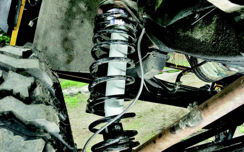
Many of the most talked-about suspensions are those which achieve huge amounts of articulation. The one Daan Schreuders built for his hybrid Land Rover was quite modest by comparison – but that just made it more worthy of comment than ever. ‘There’s no dislocation,’ he told us, ‘but proper ten-inch travel, very well balanced between front and rear.’ This was achieved using 220kg Old Man Emu front and 170kg Range Rover rear springs, which provided about an inch of lift, and running identical 10” Pro-Comp shocks at each corner.
To locate the axles, Daan used rubber-bushed radius arms all round. Up front he fitted Range Rover units, which he drilled to save weight, while those at the rear were fabricated in T45. Unusually, the rear axle wasn’t located using an A-frame: instead, Daan fitted a panhard rod.
It’s not unusual to see vehicles on which one axle does way more work than the other, with drivers constantly banging their diff-locks in and out to try and compensate. Even a standard Suzuki Samurai will cover the ground well, however, simply because both ends are working together rather than fighting each other, so the reasoning behind Daan’s design is surely sound.
Still want proof? How do 13th in the Rainforest Challenge and 6th in class at Ladoga sound? That’s what you can achieve in a vehicle that’s built not to prove a point, but to do the right things really well.
Making the most of leaves
One of the first extreme-suspension vehicles we ever featured in TOR remains one of the very best Britain has ever seen. At a time when winch challenges were dominated by highly specced-up 90s and Ibexes, Willie Davenhill’s Lightweight humbled them all time after time in the toughest events of the lot.
Being one of the first competition trucks to be fitted with portal axles certainly helped. But credit where credit’s due – it did it all on leafsprung suspension.
Many ways have been developed to make leafers flex better – mainly in America, where so many old Jeeps, Broncos, pick-ups and early Land Cruisers are still going strong. And Willie used as many of them as he could find.
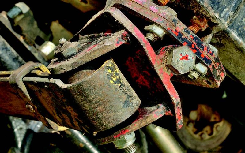
The springs themselves were TI Console parabolics – already more flexible than a standard leaf pack. Mated to Pro-Comp ES9000 shocks, they were mounted using a combination of pivoting mounts at the front and revolver shackles at the back.
The former allow the spring packs to twist further than standard springs to let the axle articulate further. On standard leaf-sprung vehicles, the springs are fixed in line with the chassis at either end and to the axle in the middle, meaning they twist when the axle articulates. It’s a bit like the torsion bars used on some independent setups.
By mounting them on a pivot, which can open up like a book, wheel travel is no longer limited by the degree to which the springs can twist as they can now follow the movement of the wheel on their pivots.
As for revolver shackles, these let the springs twist further than fixed shackles – it’s the same logic as the pivot mounts on the front end. In addition, however, the shackles are able to open out as ground pressure unloads, providing a lot more in the way of wheel travel – without the massive increase in ride height that would result from more conventional extended shackles.
The whole lot was mated to a set of Pro-Comp ES9000 shock absorbers, which were attached using custom upper and lower mounts incorporating a brace to prevent them from flexing under extreme articulation. These shocks were capable of extending to a full length of 32”, and Willie told us he reckoned the truck used every bit of that over rough ground. ‘I think I take wheel travel a little bit for granted nowadays,’ he said wryly. ‘Maybe I should drive a standard coil-sprung 90 for a while by way of a reality check!’
Thinking outside the box
Suspension design is all about engineering, and so is building a car from scratch. Mark Sealy is the engineering director for a global company, so you wouldn’t expect the off-roader he built to be anything less than exemplary.
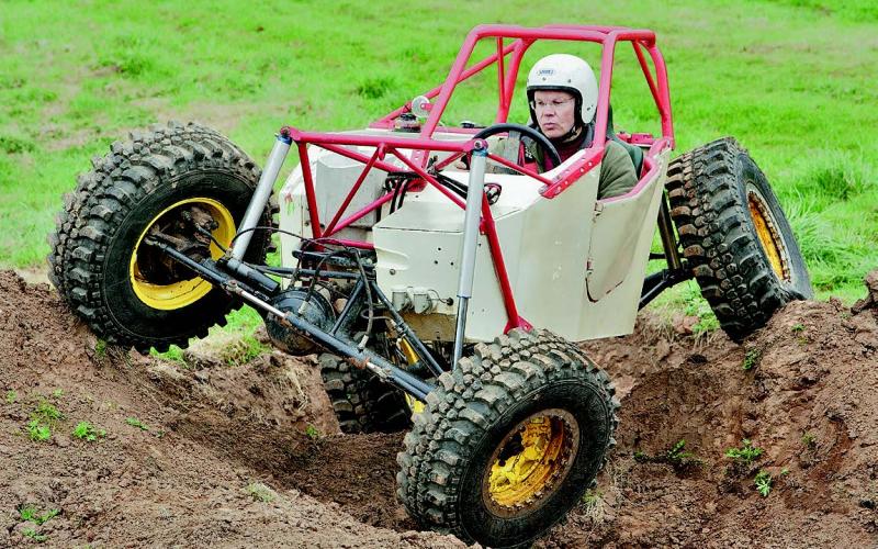
You’ve probably looked at it already and concluded that yes, exemplary it most certainly is. It’s just a set of parts hung off the tub and frame in which he sits beside a Citroën BX engine. If simplicity is good, this is brilliant.
It all ends up at a pair of widened Suzuki axles, both of which are located by lower trailing arms and upper A-frames. The axles’ movement is controlled by a set of Fox nitrogen-air shocks, which do away with the need for conventional springs and allow 14” of travel at every wheel.
Translated into the real world, this means any wheel can be lifted to just shy of four feet off the ground before any of the others think of budging. Which, further translated into the real world, means a car which can be driven over almost any terrain without being thrown out of true.
Independent suspension needn’t be a barrier
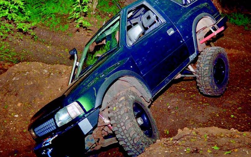
Making a Frontera flex sounds like one of those projects that’s right up there with trying to nail jelly to the ceiling. But Steve Sales’ 3-door proves that it can be done – even without swapping the independent front end for a live axle.
This was the third Fronty he built, and his previous experiences had taught him a bit about the technical side – such as not to go OTT with the lift. ‘I had some idea as to what worked and what didn’t. For example, don’t lift the front too high, as the torsion bars stiffen up too much and stop working effectively.’
In the end, Steve went for a lift of approximately 1.5”, using small spacers and a ball joint flip up front rather than cranking the life out of the radius arms – enough to add some clearance and free up space for a set of 32” tyres, but not to turn a good truck into an unusably extreme one. He did, however, free up as much articulation as possible, using +4.5” shocks at the back and removing the anti-roll bars to let the springs do their job.
He also used relocation cones at the chassis to let the springs drop out as the axle droops, coaxing yet more travel out of the set-up. When we spoke to him, he was about to redesign this system to make it more robust and take some stress off the springs themselves, which would see them becoming captive up top and dislocating at the axle mount, but he’s very clear about one thing: ‘Mild not wild has worked!’ Even today, you still see trucks whose builders seem to have thought that the way to get round the problems created by independent suspension is to lift the body by some ridiculous distance. All you create there is a scaled-down monster truck, with vast tyres but no ability to follow the ground, and Steve’s Frontera is the opposite of that.
Listening to others is always a good idea, and another tip from Steve is that if you’re lifting a Fronty, remake the front diff brackets to drop its position so the driveshafts aren’t constantly working at a savage angle. Fail to do that, and your CV joints will soon let you know about it. That’s the case even on supposedly ‘mild’ builds like this. There’s no point in creating something unusable – and bearing that in mind will help you create an off-roader that works better than the outlandish stuff anyway. Just look at the flex Steve’s Frontera achieved and you’ll understand exactly what we mean.
Simply a timeless masterpiece
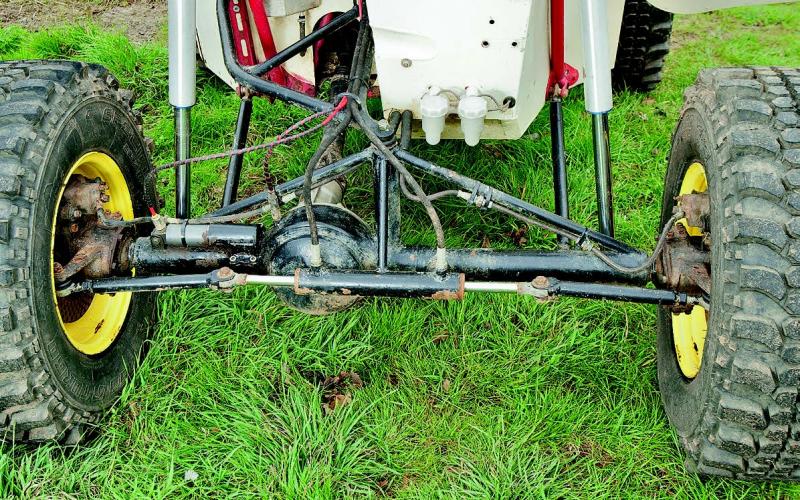
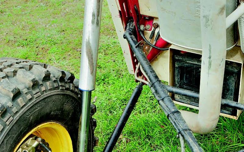
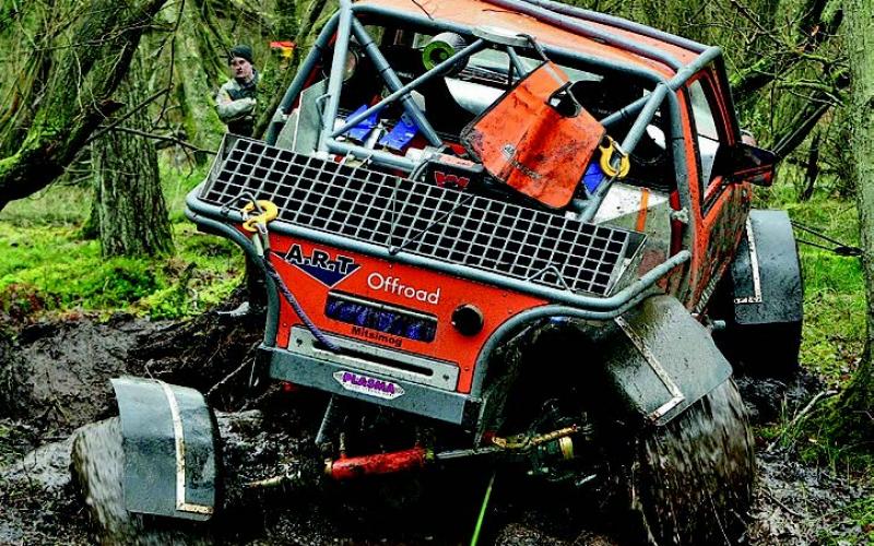
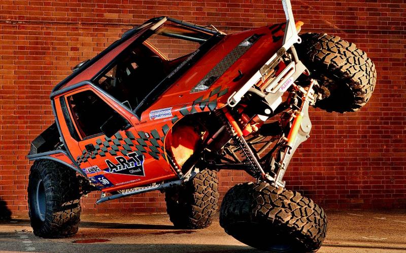
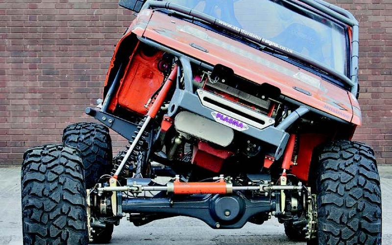
As one of the first super-trucks, Rob Tunnah’s Mitsimog was a true game-changer. Into a world of jacked-up Land Rovers on 35” tyres came his overwhelming work of four-wheeled art boasting portal axles, four-wheel hydro-steer and everything else you could think of besides. Most of all, the Mitsimog ran a twin-tank hydraulic suspension system allowing the height of all four wheels to be controlled independently. That’s only half the story, though. What made it so well suited to extreme off-roading, rather than just pulling stunts in car parks link a vulgar lowrider, was an axle location set-up Rob designed and fabricated himself using strong but lightweight 38mm o/d, 16-gauge wall T45 tube. To make it even stronger, this was twintubed and seam-welded throughout.
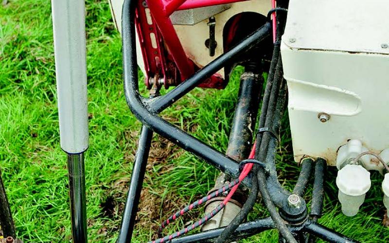
The front axle used what Rob described as ‘an upside down version of a Land Rover’s back end.’ Underneath the axle was an A-frame mounted using a single ball joint at the chassis end, then two full trailing arms ran to its upper side via high-angle joints. The A-frame was cranked to keep it as far from the ground as possible.
Rob even made the joints himself, by machining a pair of agricultural spherical bearings so they would follow the radius of the ball joint in order to achieve a high angle of movement. There were two of these bearings on top of the axle and one at the back of the A-frame; for the other joints in the system, Rob used simple Land Rover pivots bushed with polyurethane.
‘The main reason for the design is to keep the car low,’ he told us. ‘If you keep the A-frame on the bottom, you can reduce the body height, and with the diff being quite big on the Unimog it lets you get the axle further up in the car as well. I’ve never seen it used before, so it was a bit untested, but it seems to work very well.’
It was simpler at the back of the vehicle, where Rob used a more traditional A-frame and trailing arms. Again, these were fitted using high-angle joints and polyurethan bushes, but with no lower body here the links could all be placed on top of the axle. ‘The theory’ he explained, ‘is that if you hit the front end on something, you can then drag the back over it if needs be.’ Once again, it was all fabricated in his own workshop.
A true pioneer among Jimnys
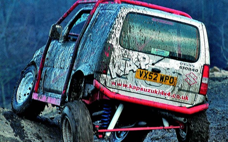
In the days before super-Jimnys, Darren Wilson at KAP built… well, a super Jimny. It was a Jimny, and it was super, so there you are. And it could flex the way no-one had seen one flex before. Darren bobtailed the Jimny, and he also shortened its wheelbase. Yes, really, a SWB Jimny. He did it by moving the spring turrets forwards, which is an interestingly alternative take on suspension mods.
‘With the articulation we were aiming for,’ he told us, ‘we wanted to make it operate in as smooth a line as possible. So we altered the pitch of them slightly, so they work at the right angle as the axle drops and the spring extends.’
Darren didn’t want to just do a copy of the dislocating suspension that was all the rage in the off-road world when he built his Jimny, so instead he designed a sliding top mount to extend the rear springs’ limit of droop. ‘When your spring goes to full articulation, inside its mount there’s a platform on a sliding mechanism. So you’ve got your spring at full stretch, and then the baseplate that the spring’s bolted to drops another eight inches.’
In combination with the longest Pro-Comp ES9000s available, this gave the vehicle a remarkable level of rear articulation. The set-up also provided a 3” lift, which was of course replicated up front.
‘Three inches is the optimum height you want to lift a Jimny,’ Darren told us, ‘because after that the panhard rod starts moving the axle to one side.’ With the combination of big lift and big articulation, however, he decided not to take any risks and fabricated a new rod in CDS. This was mounted as close as possible to the end of the axle on the passenger’s side and to the wheel on the driver’s side, where it picked up on the chassis, giving it the longest possible sweep to let it work correctly.
The suspension itself was less complex at the front, with KAP’s own +3” springs controlled by another set of ES9000s. Off came the anti-roll bar to free up more flex, then he went back into the workshop to develop what he called his Twister radius arms.
‘The standard radius arms on the Jimny are happy to swing down, but not across,’ he explained. ‘The bush is perfect for droop, but of course on articulation the radius arm is pulled slightly to one side. The bushes try to restrict it somewhat – and what happens is you kill them.
‘The Twister mechanism is fitted directly after the bush. It uses some threaded bar into a threaded tube, so that it doesn’t restrict the movement of the axle. The difference is phenomenal. It can rotate, meaning it doesn’t restrict any part of the articulation.
‘On top of this, the front radius arms are not very strong – we had to brace them up on the original Jimny we did. So we’re killing two birds with one stone.’
So there you have it – an instant masterclass on Jimny suspension from one of the first people to turn it into something special. A small aside to make is that the Jimny he did all this to only had 86 miles on the clock, and you’ll be doing very well to match that. But if you plan to turn one of these little giant-killers into an offroad hero, this one was the work of a man who really, really knows his Jimnys.
Want to push the limits? Be warned: they might push back…
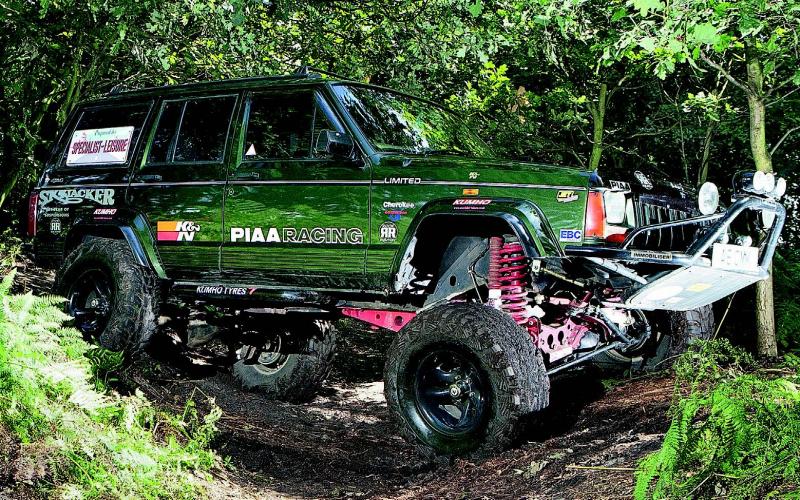
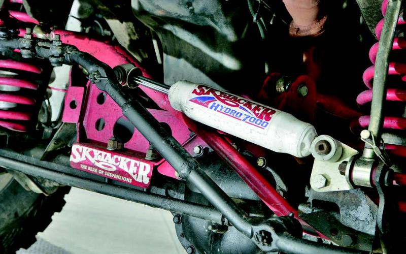
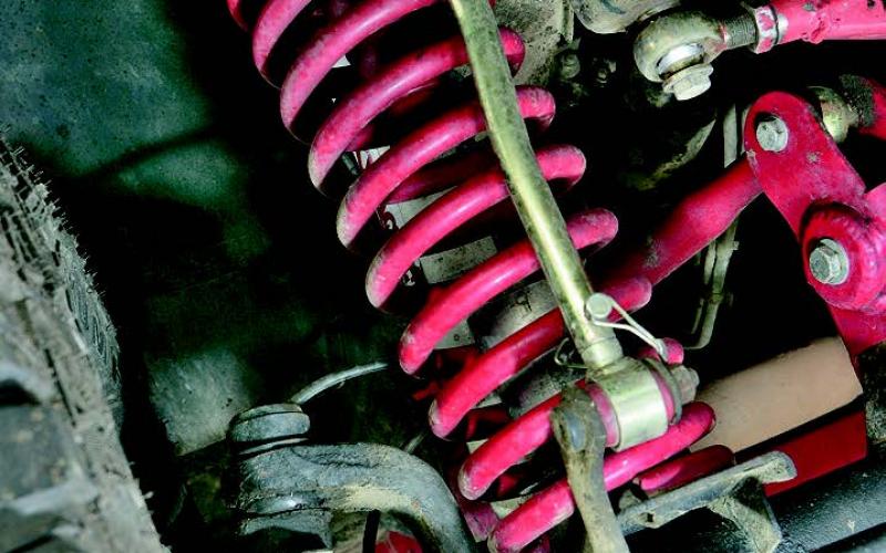
Suspension can be big, and it can be clever, and it can be big and clever. Too much is definitely too much, but lots of height can add lots of flex. It can give you lots of grief too, though. Skyjacker is well known in the USA as a leading suspension brand, and the company’s systems have been used to put extra inches beneath a wide range of trucks. Among these is the Jeep Cherokee XJ, for which the company’s product line includes the +8” Rock Ready kit.
As far as we’re aware (and we asked Skyjacker themselves), Ged Wade was the first person in the world to fit one of these on a RHD Cherokee. As if taking on the attendant hassles of putting such a monster lift under his vehicle wasn’t enough, he did it using a set of parts designed for Jeeps with the steering wheel on the left – and he did it without anyone else’s efforts to refer to. Brave.
The front panhard rod that came with the kit was completely useless with RHD, for starters, so a replacement had to be made up from scratch. Plenty of trial and error there. And that was the easy bit – three whole days went into the steering linkages. ‘The mechanics could modify the angles and then take the car for a spin to see how they worked,’ Ged told us. ‘It was certainly a test of their patience, but they got there eventually!’
The solution turned out to be to blend the Cherokee’s existing components with the replacement parts provided by Skyjacker. So the factory-fitted steering arms were removed, cut about and welded to bits of the Skyjacker kit, and a similar process saw the pitman arm and steering
damper being re-routed.
That’s the sort of soul-destroying (and possibly vehicle-destroying) process you’ve got to go through if you take it upon yourself to pioneer something. As people always say about modifying a vehicle, you’re messing about with systems that the original manufacture spent years perfecting – but at least normally you’re doing it using bits that an accessory manufacturer spent years perfecting so it would work.
In this case, Ged wasn’t just pushing the boundaries – they were pushing back. But he succeeded in the end, and his +8” Cherokee became a daily driver as well as a notably able off-road toy. The real story here, though, is how much effort it took to get there. Definitely a cautionary tale…
More length means more flex
Extending a Land Rover’s wheelbase by using longer rear suspension links has become a recognised technique in hardcore vehicle-building circles. But Tim Farley gave it a go almost a decade back, when he set to work on modifying a 90 along the lines of what he’d seen in America.
‘I think people in the UK, probably because of trialling, are infatuated with short, tiny vehicles,’ he said. ‘A longer, wider vehicle just gives you so much more stability.’ With that in mind, he aimed to extend the 90’s wheelbase to 102” – with all the extra length coming from the rear axle.
This was held on by an extended A-frame and custom cranked trailing arms made from 7mm wall CDS – strength is definitely an issue when a link has to span such a long distance (a little more than 9” longer than standard), hence the super-duty material. Rose joints were used throughout – the only part of the suspension to stay with standard pivots was the radius arms’ chassis mounts.
These were part of what was the second three-link system Tim had designed. And he learned from the first. ‘There’s more vertical separation between the links this time,’ he told us. ‘So it holds the axle more stable. I used the existing transmission crossmember and strengthened it up, and then we built all the links.’ The separation was achieved by dropping the axle mount for the centre link, creating an element of triangulation at the axle end; the rose joints used here mean there are no extra limits on articulation imposed by doing this.
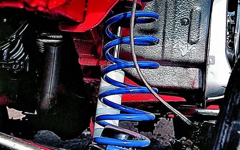
After all that, it seems almost comical that Tim chose police-spec Range Rover springs for the front of the vehicle ‘because they’re £8 each… and they’re really soft and supple.’ The same reasoning was behind his choice of ’second-hand knackered old ones’ at the back, where it’s so light that anything else was simply too hard. Also keeping with the money-saving theme were the 14-inch Pro-Comp ES9000 shocks he used all round. ‘Most of the long-travel set ups run the front shocks outside the springs,’ he said.
‘I’ve never really understood why; when we built our first one, I put them inside and they didn’t seem to foul anywhere. All we needed to do was put on a spring retainer at the bottom which holds the shock as well, and that keeps the shock protected inside the spring.’
Three-link is not enough…
We said Richard Wattam was going to put in another appearance before this article was done. And here it is.
The story starts when Paul Ruddick presented Richard with two Suzukis. One was still on leaf springs: the other, which he’d just bought, had 3-link coil-sprung suspension – but enough axle steer to have driven its builder to despair. The plan was to strip the dodgy coiler and, with Richard’s engineering skills ensuring no further horrors would be unleashed, turn the leafer into the kind of three-link Suzuki nobody would frown at.
‘I didn’t want to do something that would make the car worse than it was,’ Paul told us. ‘I’d fallen out of love with it because of the way it rode on the leaf springs. The choice was to coil it, or buy a Land Rover instead.
‘Richard worked out all the dimensions so that the three-link system would work properly. I just supplied him with a set of shocks and springs, and everything else he manufactured himself from raw materials.’ Those springs were 14” Rally Design coils, rated at 225lb all round, while the shocks were Rough Country units with 14” of travel up front and 16” at the back. He reckons the whole lot cost about £330: ‘Cheaper than buying a good set of leaf springs!’
The system Richard built around them used linkages made from CDS with a 6mm wall thickness, so it wasn’t not very light but sure was strong. Front and rear radius arms were attached to the chassis at a pair of common mounting cradles, and centre links at each end ran to the tops of the axle cases. So as to prevent binding on the bushes, the axle ends of the radius arms and the chassis ends of the centre links were attached using rotating joints, and up front the shocks were mounted ‘before’ these on the links themselves so as to follow the suspension faithfully throughout its full arc of movement. Finally, as with Richard’s own vehicle (see above), panhard rods were used front and rear to keep the axles in line.
The result? Nothing short of brilliant, Paul told us. ‘It’s very smooth, the way the suspension flexes. It keeps the car more balanced and stable.’ Axle steer became a thing of the past, and Paul found that the angle of the diff noses remained unchanged however twisted the axles got.
Like Daan Schreuders, whose Land Rover is to be found elsewhere in this article, Paul wasn’t interested in performing absurd tricks with articulation to impress his friends. That’s why the springs were clamped top and bottom with no ability to dislocate. To Paul, stability mattered more than wringing every last degree out of the system’s potential for wheel travel – and with that in mind, his Suzuki kept its wheels on the ground very smoothly indeed.
Bringing extreme articulation to the Rover-legal world
Long travel has always been the holy grail for suspension builders, but as dislocating systems started taking off they threatened to leave many 4x4 drivers behind. The reason? They weren’t allowed by the ALRC. That’s who Darren Slater trialled with, and he decided to do something about it. The result was a suspension system giving extreme articulation without falling back on dislocation.
Now, dislocating systems have their fans, but they have their critics too. The notion of a wheel hanging down so far it touches the ground despite having almost no weight on it offends many, who ask what the point is when it’s barely able to get any traction anyway, so Darren’s set-up was interesting to more than just his mates in ALRC.
‘Interesting’ as in they wanted it for themselves. So Darren set up in business to make and sell the system, which he developed for the Defender, Mk1 Range Rover and Discovery Tdi.
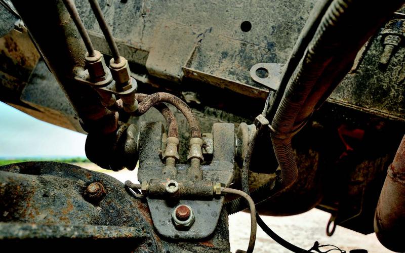
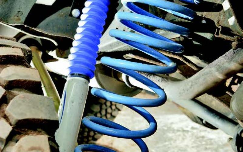
The full kit included springs and shocks, radius arms and trailing links, a custom rear prop, shock mounts, rear axle shock brackets and spring retainers and extended brake flexis. ‘The main part of it is the non-dislocating spring,’ Darren told us. ‘It stands at 22” as a free length; it’s about half that for a standard spring. The springs we’re using will compress up to 9”, but they will expand to about 24” with the axles at full droop. In terms of lift, the vehicle went up by about 3”.
Darren ran the springs with Pro-Comp ES9000 shocks, fitted using higher front turrets and repositioned rear brackets, which allowed around 17” of droop below the chassis line. The limiting factor was the A-frame ball joint – something that couldn’t be remedied at the time, though rose-jointed solutions have become commonplace since then.
It’s ironic that the ALRC outlawed dislocating suspension when these systems were just making the most of the fact that Land Rover didn’t make their springs fully captive in the first place. But like any good engineer, Darren saw this restriction as an opportunity – and as his Discovery shows, he didn’t half take it.
Less is more if you make the most of it
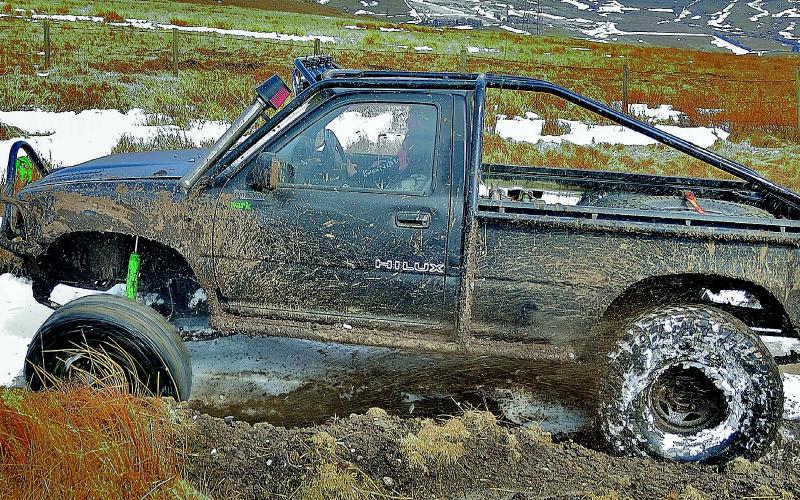
There’s nothing very out of the ordinary about +2” springs, be they leaves or coils. But Ashley Stimpson was happy to make do with that when he built his Hi-Lux. Not just that, of course, otherwise it wouldn’t exactly be worthy of a place in an article like this. But he bought it with them in place and decided that instead of changing them for something with more arch, he’d look for ways of improving the way they performed.
This was already pretty good, with +15” front and +9” rear shocks providing them with plenty of scope to do their work. Ashley fitted a modest 1” body lift and went at it with the tin snips to make room for 35” tyres, then presented the Hi-Lux with its secret weapon – a set of buggy links which he made himself using a set of suspension top links from a Nissan Patrol.
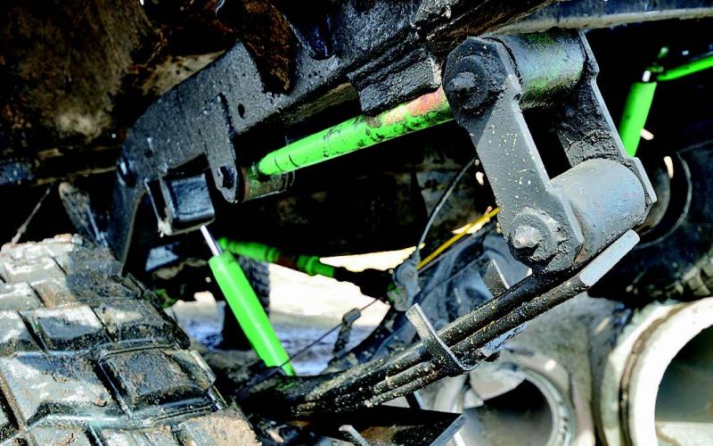
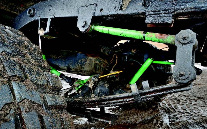
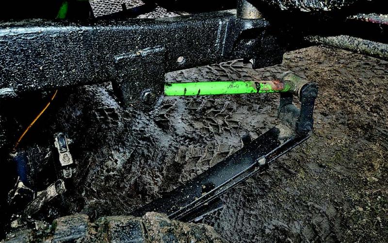
These could be described as the leaf-sprung equivalent of dislocation cones. They provide a pivoting link between the back of the rear springs and their mounting points which normally stays closed but can swing down as the axle goes to droop – adding several inches to the amount of vertical travel on offer. Ashley also made up a set of guides to keep them tidy as the axle returns to rest and stop them from slopping around and trashing the chassis mount bush when they’re closed up.
With articulation clearly an issue, though, why didn’t Ashley just fetch the leaf packs off and fit a set of coil springs instead? Well, for one thing his Hi-Lux proves that you don’t actually need to turn your back on the old technology to built a great truck, just think about how to make the most of it.
And besides, he has another answer – which not many people who’ve gone to coils will have thought about until afterwards. ‘With the leaf springs, there’s only eight bushes throughout the truck. My old Nissan Patrol had three times that. That’s three times the effort, and three times the expense.’
Doing it the American way…
Gary Andrews only got involved in off-roading because some of his mates were doing it, but he didn’t waste time getting down to work on building a car you’d expect from an old hand. ‘I got an 88” Series III with no engine or box and built a virtually standard V8, he says. ‘Almost straight away, I realised you needed more than that. I had a mate who was into rock crawling and saw some of the technical features in American magazines. I thought “So that’s what you do,” and set about building something similar.’
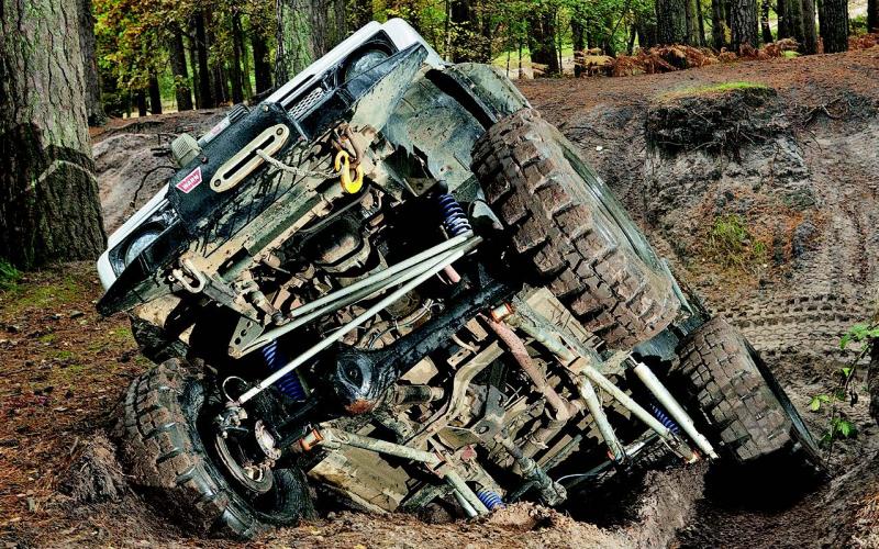
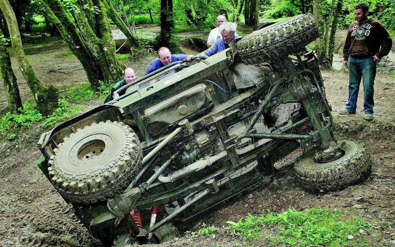
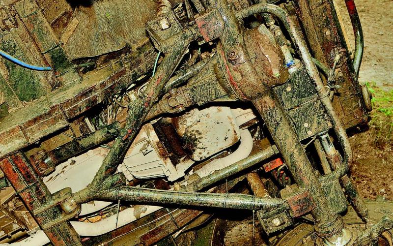
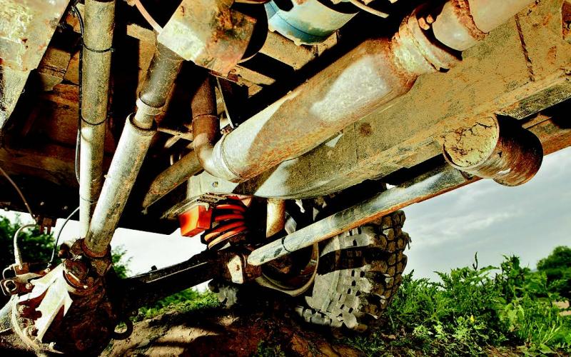
The result was a Landy with a home-brewed suspension system giving it a monstrous five feet of articulation. That’s how high you could lift one wheel on the end of a Hiab without any of the others leaving the ground. Helpfully, Gary parked the Landy on its side while we were taking pictures of it, so you can get a better idea of what’s going on underneath.
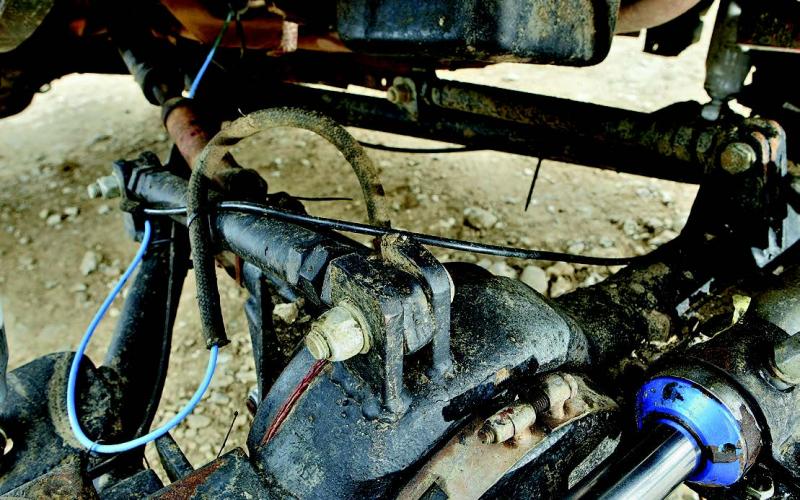
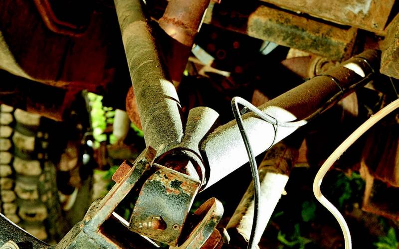
Look at the front; a triangulated, single-link A-arm is pivoted at the centre point of the chassis: ‘This gives you no bind on the twist,’ he says. The front suspension is provided by 15” Pro-Comp shocks and springs with X-Eng X-Flex springs inside instead of dislocation units. The rears are Pro-Comps, but with a dislocation system Gary made himself.
The lengthened trailing arms anchor in a Rubicon Supa-Flex front pivot point mounted in Gary’s own housing. The home-made A-frame is also over-length on standard, and the whole lot is controlled by US-sourced shocks with 12” of travel.
…and showing the Americans how to do it the British way
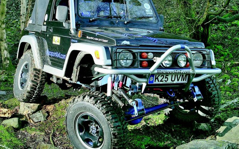
‘I’ve always liked to see suspension flexing,’ says Andy Barlow. ‘There’s something about that cross-axled look.’ So what did he buy? A Suzuki Samurai. Famous for many things but, in standard form at least, not for the suppleness of its springs. It didn’t stay in standard form for long. Andy actually left the truck alone in several areas many off-roaders would consider essential, but when it came to the suspension he went to town. He had a lot of support from Paul at Macsport 4x4, who designed the entire front end. But between them they also got no small amount of discouragement by the simple act of going on to a certain US off-roading forum. Ask for advice in the wrong place, and out come the trolls: what the hell do you know, we tried that ten years ago, you’re all communists anyway, etc. When wise men speak, you listen: when morons shout, you walk away.
Which is just what they did, straight to the workshop – where he built himself a Suzuki that proved the keyboard warriors wrong.
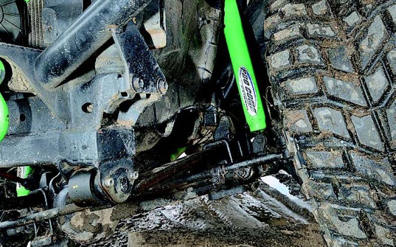
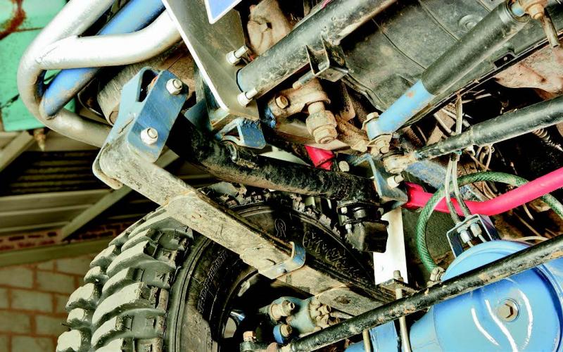
Up front, the system uses a swinging front mount for the spring – similar to the buggy links on the rear springs of Ashley Stimpson’s Hi-Lux, which is featured a few pages further back in this article. This allows a much-improved level of droop, with the swinging arm dropping out as the weight on that corner unloads. Paul reassured us that smaller bumps don’t unsettle it, with the spring itself doing all the work on the road, so the links stay in place and handling at higher speeds isn’t compromised. Side-to-side movement, meanwhile, is controlled by a panhard rod, and relocation plates guide the swinging arms back into place as the ground levels out.
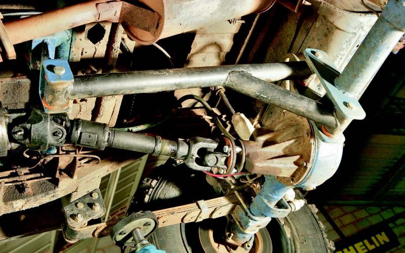
Talking of the springs, they’re from a Jeep Wrangler YJ – a common source of upgrades when you’re modding a leafer. At the back, Paul and Andy built a three-quarter elliptic rear set-up using half a leaf and missing rear links – if that sounds like gobbledygook to you, don’t worry, because a) you’re not alone, and b) the pictures tell the story better than words ever could.
Which Andy would appreciate, because he liked his Samurai to look its best. ‘I don’t want to just have a capable off-roader that looks rubbish,’ he told us. ‘It’s got to look right.’ Which, of course, meant lots of flex. Job done.


